


In modern packaging operations, the ability to apply a metal screw cap at high speed without compromising seal integrity is one of the most technically demanding challenges on any filling line. As production volumes climb and consumer expectations for tamper-evident, airtight packaging grow more stringent, manufacturers across food, beverage, pharmaceutical, and specialty chemical sectors are investing heavily in automated capping technology. Understanding exactly how these systems work — and why the metal screw cap presents unique mechanical and process considerations — is essential for any operations or packaging engineer evaluating line performance.
The metal screw cap is not simply a closure — it is a precision-engineered component that must interact correctly with container threads, liner materials, and torque application systems simultaneously. High-speed automated capping lines are designed to manage all of these variables in a controlled, repeatable sequence, often applying hundreds or even thousands of caps per minute. This article walks through the full mechanical and process logic behind how these lines handle a metal screw cap, from cap feeding and orientation through torque control and final seal verification.
The Mechanical Journey of a Metal Screw Cap Through an Automated Line
Cap Feeding and Singulation
The process begins well before the metal screw cap ever contacts a container. Bulk caps are loaded into a hopper or vibratory bowl feeder, which uses controlled vibration and track geometry to orient each cap correctly. Because a metal screw cap has a defined top and bottom profile — typically a flat or embossed top panel and a threaded skirt — the feeder must reliably distinguish between correctly oriented and inverted caps.
Vibratory bowl feeders accomplish this through a combination of track width, ramp angles, and air jets that reject misoriented caps back into the bowl. The result is a continuous, singulated stream of correctly oriented metal screw caps delivered to the pick-and-place or chuck capping head at a rate matched to line speed. Any interruption in this feed stream causes a line stoppage, which is why feeder design and cap geometry compatibility are critical selection criteria.
For larger-diameter metal screw caps, such as those used on wide-mouth jars, some lines use an elevator and waterfall feed system rather than a vibratory bowl, as the larger cap mass can cause jamming in conventional bowl feeders. The choice of feed mechanism is always matched to the specific metal screw cap diameter, weight, and surface finish.
Cap Transfer and Placement onto the Container
Once singulated, the metal screw cap moves along a chute or conveyor to the capping station. At this point, the cap must be placed onto the container mouth with sufficient accuracy to allow the capping head to engage the threads cleanly. Misalignment at this stage — even by a few millimeters — can cause cross-threading, which damages both the cap and the container finish.
Inline capping machines typically use a cap delivery chute that positions the metal screw cap directly above the container as it passes beneath. The container's upward motion or a downward cap placement mechanism seats the cap loosely on the container mouth before the capping head engages. Rotary capping machines use a starwheel to hold containers in precise registration while a rotating turret of capping heads descends to engage each metal screw cap in sequence.
The precision of this placement step is especially important for metal screw caps because tinplate and aluminum closures have less flex than plastic caps. A plastic cap can self-correct minor misalignment during application; a metal screw cap requires more accurate initial placement to avoid thread damage or incomplete seating.
Torque Application and Thread Engagement Mechanics
How Capping Heads Apply Torque to a Metal Screw Cap
The capping head is the heart of the automated capping line. For a metal screw cap, the head must apply a precisely controlled rotational torque while simultaneously applying downward axial force to ensure the cap threads engage fully with the container finish threads. Most modern capping heads use a magnetic clutch or electronic torque control system to set the exact torque value required for each specific metal screw cap and container combination.
The capping head grips the metal screw cap using a chuck insert — a rubber or polyurethane sleeve shaped to match the cap's outer profile. As the chuck rotates, it drives the cap onto the container threads. The magnetic clutch disengages automatically when the preset torque value is reached, preventing over-tightening that could strip threads, deform the cap skirt, or damage the liner inside the metal screw cap.
Electronic servo-driven capping heads offer even finer control, recording the torque curve for every single metal screw cap applied. This data can be used for statistical process control, allowing quality teams to detect gradual drift in torque values before it results in defective seals. For pharmaceutical and high-value food applications, this level of traceability is increasingly a regulatory or customer requirement.
Thread Engagement Depth and Liner Compression
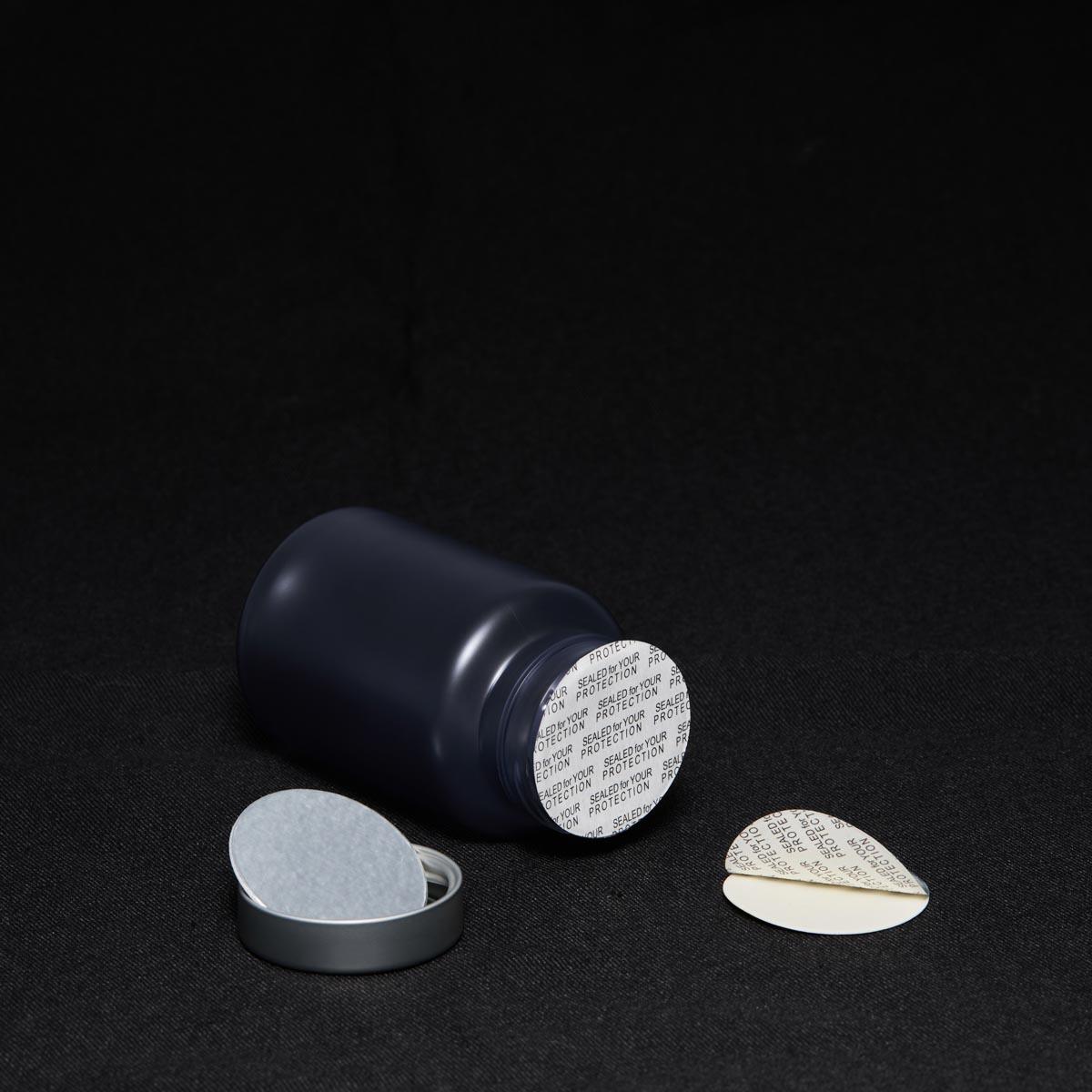
A metal screw cap typically contains a liner — a disc of foam, plastisol, or composite material bonded to the inside of the cap top panel. This liner is what creates the actual hermetic seal when the cap is applied. For the seal to function correctly, the liner must be compressed to a specific depth against the container's sealing surface, which is determined by the thread engagement depth and the torque applied.
Automated capping lines are calibrated so that the combination of thread pitch, cap height, and applied torque results in the correct liner compression for each metal screw cap size. If torque is too low, the liner is under-compressed and the seal may leak or allow oxygen ingress. If torque is too high, the liner can be over-compressed, causing it to extrude beyond the sealing surface and potentially compromising the seal's long-term integrity.
This balance is particularly important for metal screw caps used on food and beverage products where vacuum sealing is required. Many tinplate metal screw caps are applied under hot-fill or steam-injection conditions that create a vacuum inside the container as it cools. The liner must maintain its seal under both the initial application torque and the subsequent vacuum-induced load.
Speed, Precision, and Quality Control at High Throughput
Maintaining Consistency Across Thousands of Caps Per Hour
High-speed capping lines may apply a metal screw cap at rates ranging from 200 to over 1,000 containers per minute depending on the machine configuration and cap size. Maintaining consistent torque, placement accuracy, and seal quality across this volume requires tight integration between the capping machine, the container conveyor, and the upstream filling system.
Container spacing and speed must be precisely controlled so that each container arrives at the capping station in the correct position and at the correct moment. Any variation in container spacing — caused by upstream filling irregularities or conveyor slippage — can result in a metal screw cap being applied off-center or with incorrect torque because the capping head engagement timing is disrupted.
Modern capping lines use servo-driven conveyors and electronic line synchronization to minimize these variations. Vision systems positioned at the capping station can detect misplaced or absent caps before the container exits the capping zone, triggering automatic rejection of non-conforming units without stopping the line.
Torque Verification and Seal Integrity Checks
After application, the metal screw cap must be verified to confirm that the correct torque was achieved and that the seal is intact. Inline torque verification systems use sensors to measure the removal torque of a sample of caps, confirming that the application torque was within specification. Some lines use non-contact measurement methods that assess cap position and thread engagement depth optically.
For vacuum-sealed products, a vacuum detection system — typically using a tap-tone or pressure sensor — checks each container to confirm that the expected vacuum level is present under the metal screw cap. Containers that fail this check are automatically diverted from the line. This combination of torque control and seal verification is what allows high-speed lines to maintain quality standards that would be impossible to achieve through manual inspection alone.
Leak detection systems using compressed air or tracer gas can also be integrated downstream of the capping station for applications where absolute seal integrity is critical, such as pharmaceutical or high-acid food products. These systems add a final layer of assurance that every metal screw cap on the line has been applied correctly.
Cap Design Factors That Influence Automated Line Performance
Diameter, Thread Profile, and Skirt Geometry
Not all metal screw caps behave identically on an automated line. The cap's diameter, thread profile, skirt height, and surface finish all influence how it feeds, orients, transfers, and applies. Wider caps require larger chuck inserts and may need modified feeder track geometry. Caps with deep skirts or embossed decorative features can create friction in the feed chute that slows delivery and causes jamming.
The thread profile of the metal screw cap must match the container finish thread profile precisely. Mismatches in thread pitch or thread start position are a common cause of cross-threading on high-speed lines, particularly when cap tolerances are inconsistent across production batches. Specifying a metal screw cap with tight dimensional tolerances is therefore not just a quality preference — it is a direct operational requirement for reliable automated line performance.
Skirt geometry also affects how the capping head chuck grips the cap. A cap with a smooth, cylindrical skirt is easier to grip consistently than one with a heavily knurled or irregular outer surface. When selecting a metal screw cap for a new automated line, it is worth testing the cap's behavior in the actual capping head chuck under production-speed conditions before committing to a final cap specification.
Liner Type and Its Effect on Torque Requirements
The liner inside a metal screw cap has a direct effect on the torque required to achieve a proper seal. Softer liners, such as expanded polyethylene foam, compress more easily and require lower application torque. Harder liners, such as plastisol or composite materials, require higher torque to achieve the same compression depth. The liner material must therefore be factored into the capping machine's torque settings.
Liner condition also matters. If a metal screw cap has been stored in high-humidity conditions, the liner may absorb moisture and change its compression characteristics. If caps have been stored for an extended period, liner hardening can occur, requiring higher torque to achieve the same seal. These variables are often overlooked during line setup but can cause significant seal quality issues in production.
For hot-fill applications, the liner must be able to withstand the elevated temperature of the product at the time of capping without deforming or losing its sealing properties. Selecting a metal screw cap with a liner rated for the specific fill temperature is essential for maintaining seal integrity through the cooling and vacuum-formation phase.
FAQ
What torque range is typically used when applying a metal screw cap on an automated line?
The torque range varies depending on cap diameter, thread profile, and liner type, but most metal screw cap applications fall between 5 and 30 inch-pounds of application torque. Smaller caps with soft liners sit at the lower end of this range, while larger caps with harder liners require higher torque. The correct value is always determined through application testing with the specific cap and container combination.
Can the same capping machine handle multiple sizes of metal screw cap?
Yes, most modern rotary and inline capping machines are designed for quick changeover between different metal screw cap sizes. Changeover typically involves swapping the chuck insert, adjusting the cap feed chute width, and reprogramming the torque settings. The time required for changeover depends on the machine design, but well-engineered lines can complete a size change in under 30 minutes.
How does a high-speed line detect a cross-threaded metal screw cap?
Cross-threading produces a characteristic torque signature — the torque rises sharply and then drops or plateaus before reaching the correct final value. Electronic torque monitoring systems can detect this pattern in real time and flag or reject the affected container. Vision systems can also detect a cross-threaded metal screw cap by identifying a cap that sits at an angle or is not fully seated on the container finish.
Does cap surface finish affect automated capping performance?
Yes, the surface finish of a metal screw cap affects both feed behavior and chuck grip. Highly polished caps can slide in the feed chute and cause orientation errors, while heavily textured caps may create friction that slows feed rates. The chuck insert material and profile must be matched to the cap's outer surface to ensure consistent grip without marking or deforming the cap during application.